New (to me) Bluetooth module (CC2540-A1)
Before the last Charlotte IoT meetup, which was about building stuff with BLE Beacon, I wanted to experiment some and see if I could get it working before the meeting and I went out and ordered some new toys – complete with a total non-understanding on what I really needed. I have a better idea now that the meetup has happened.
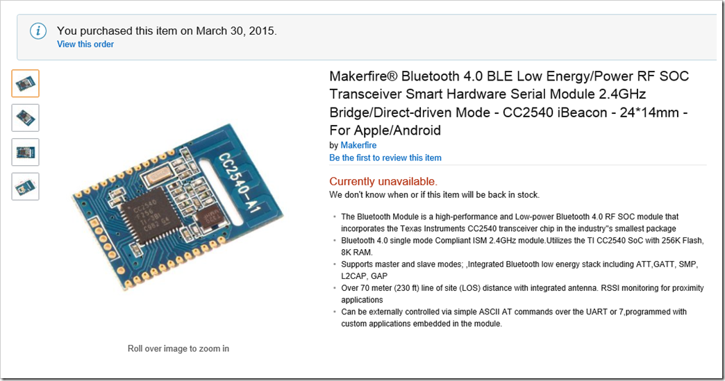
In the process, I found this pretty cool looking BLE module on Amazon the other day for 8$ each (of course, it is now out of stock)…
The Product description was super helpful or at least very technical looking but missed a few details that would be nice – like a link to a datasheet or schematic, or pinout…
Eventually I found the company that manufactured it – and the specs are light on their website, too – same as the Amazon page, really… (http://en.szrfstar.com/product/2/BLEmodule/93.html)
This is fine – I’m used to a minor amount of detail on the Amazon page, but there is almost always a ton of data sheets on the web… except… for… this… module.
I spent the better part of a week of random attempts looking for the pinout diagram or a list or SOMETHING so I could figure out how it was supposed to be hooked up.
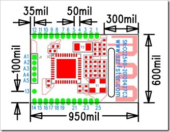
I still haven’t searched for the control details… but I did at least find something of a pinout and some related details from this site: http://www.cnblogs.com/szsammy/archive/2013/05/14/szsammy.html, which required a bit of translation to read it.
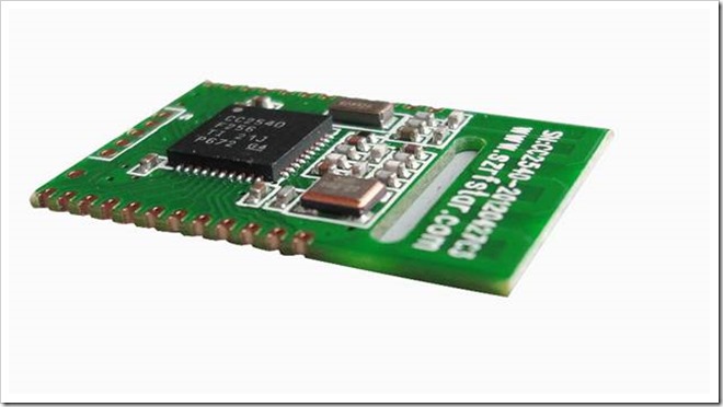
That looks pretty close to the original, and it is by the same company – model number matches and the spec look pretty corresponding, so that’s good.
We have a pinout from the site… it has most of our numbers in here, looks sane as well.
Pin Number | Pin Name | Description |
1 | VCC | 2-3.6V power supply |
2 | GND | Power Ground |
3 | P2.2 | Digital I/O |
4 | P2.1 | Digital I/O |
5 | P2.0 | Digital I/O |
6 | P1.7 | Digital I/O |
7 | P1.6 | Digital I/O |
8 | U-N | USB |
9 | U-P | USB |
10 | P1.5 | Digital I/O |
11 | P1.4 | Digital I/O |
12 | P1.3 | Digital I/O |
13 | P1.2 | Digital I/O |
14 | P1.1 | Digital I/O |
15 | P1.0 | Digital I/O |
16 | P0.7 | Digital I/O |
17 | P0.6 | Digital I/O |
18 | P0.5 | Digital I/O |
19 | P0.4 | Digital I/O |
20 | P0.3 | Digital I/O TXD |
21 | P0.2 | Digital I/O RXD |
22 | P0.1 | Digital I/O |
23 | P0.0 | Digital I/O |
24 | RESET-N | Low reset |
25 | GND | Power Ground |
A1 | GND | Power Ground |
A2 | VCC | 2-3.6V power supply |
A3 | P2.2 | Digital I/O,DD |
A4 | P2.1 | Digital I/O,DC |
A5 | RES | Low reset |
So far, I have checked continuity on the Ground and VCC pins, and they check out as expected.
Next up, solder some wires on and see if I can get a connection… and maybe even some data.
I’ll update here as I have more info


debra galley April 13, 2015 3:33 AM
cool stuff